By Martin Harris.
How to Calculate Static Pressure Loss in Your Ductwork
To calculate static pressure loss, add up the resistance of every piece the air passes through on your worst branch: the hose, the straight duct, the elbows, the wye, the filter, and any separator. Look up each piece in a published loss table, total the column, and check that total against your collector's fan curve. The example below does this for a small garage layout using the component values Oneida publishes.
Static pressure is measured in inches of water column, which I write as in. w.c. from here on. If that term is new, start with my plain language guide to dust collector static pressure. This page is the math. It is also one step in my larger dust collection system design guide.
What you need before you start
- A floor sketch. Spiral Manufacturing's design guide tells you to draw the shop to scale on graph paper. Mark each machine, where its dust port is, where the collector goes, and the path with the fewest turns.
- Lengths. Measure the straight duct and the flex hose on each branch, in feet.
- A fitting count. Count the 90 degree elbows, 45 degree elbows, and wyes on each branch.
- Filter and separator losses. Check your collector's manual or ask the maker. If you run a cyclone or a baffle, you need a number for that too.
- The collector's fan curve. This is the chart that shows how much air the collector moves at each static pressure. You use it at the end.
The loss values
These are the 4, 5, and 6 inch columns from Oneida's component loss table. The full table, with 3, 7, and 8 inch sizes, is on my dust collection ductwork guide.
| Component | Unit | 4 in | 5 in | 6 in |
|---|---|---|---|---|
| Rigid duct | per 5 ft | .285 | .230 | .185 |
| Flex hose | per 1 ft | .280 | .225 | .180 |
| 90° elbow | each | .450 | .531 | .564 |
| 45° elbow | each | .225 | .266 | .282 |
| 45° wye | each | .375 | .354 | .329 |
Values in in. w.c. Source: Oneida Air Systems static pressure component data, measured at approximately 4,000 FPM and sea level.
Four rules for reading the table:
- Rigid duct is listed per 5 feet. Divide your length by 5, then multiply by the table value.
- Flex hose is listed per 1 foot. Multiply your length in feet by the table value.
- Fittings are listed per piece. Multiply the count by the table value.
- The values assume air moving at about 4,000 FPM. FPM is feet per minute, the speed of the air. Resistance goes up with the square of air speed. Bill Pentz's static pressure notes use the formula velocity pressure = (FPM ÷ 4,005) squared. By that formula, air at 3,000 FPM has a little over half the velocity pressure of air at 4,000 FPM. So in a pipe where your air moves slower than 4,000 FPM, the table gives a loss that is higher than real. For planning, I am fine with an estimate that runs high.
The example shop
This is a sample layout for the math, sized like a one or two car garage. The collector sits in a back corner. A 5 inch rigid main runs along the back wall. Two tools hang off it: a planer near the collector and a table saw at the far end. Each tool has a 4 inch rigid drop coming down from the main, a blast gate, and a short piece of 4 inch flex hose to the machine port.
With blast gates, only one branch is open at a time. Spiral Manufacturing's method says to calculate every branch, then carry forward only the branch with the highest loss. In most shops that is the tool farthest from the collector, so I start with the table saw.
Step by step: the table saw branch
Follow the air from the saw back to the collector and write down every piece it passes through.
- Flex hose at the saw. 3 feet of 4 inch flex. 3 × .280 = .840.
- Rigid drop. 10 feet of 4 inch duct. 10 ÷ 5 = 2. 2 × .285 = .570.
- Elbow at the top of the drop. One 4 inch 90 degree elbow = .450.
- Wye into the main. One 45 degree wye, using the 4 inch branch column = .375.
- Main line. 20 feet of 5 inch duct. 20 ÷ 5 = 4. 4 × .230 = .920.
- Turn in the main. One 5 inch 45 degree elbow = .266.
- Elbow into the collector. One 5 inch 90 degree elbow = .531.
- Filter. Use your maker's number. For this example I borrow the 1.50 in. w.c. filter loss from Spiral Manufacturing's own worked example. Treat it as a placeholder.
- Separator, if you have one. Oneida suggests budgeting about 2 in. w.c. for a cyclone as a starting point. Real separator loss depends on the model and the airflow.
| Component | Math | Loss (in. w.c.) |
|---|---|---|
| 4 in. flex hose, 3 ft | 3 × .280 | .840 |
| 4 in. rigid drop, 10 ft | 2 × .285 | .570 |
| 4 in. 90° elbow | 1 × .450 | .450 |
| 4 in. 45° wye | 1 × .375 | .375 |
| 5 in. rigid main, 20 ft | 4 × .230 | .920 |
| 5 in. 45° elbow | 1 × .266 | .266 |
| 5 in. 90° elbow | 1 × .531 | .531 |
| Duct and hose subtotal | 3.952 | |
| Filter (placeholder) | maker's figure | 1.500 |
| Total, no separator | 5.452 | |
| Cyclone or separator (starting figure) | about 2 | 2.000 |
| Total, with separator | 7.452 |
Duct values from Oneida's component table. Filter placeholder from Spiral Manufacturing's worked example. Separator starting figure from Oneida.
Check the other branch
Now run the planer branch the same way. Say it has 2 feet of 4 inch flex (.560), 5 feet of 4 inch drop (.285), one 4 inch 90 degree elbow (.450), one wye (.375), 8 feet of 5 inch main (8 ÷ 5 = 1.6, times .230 = .368), and the same 5 inch 90 into the collector (.531). That branch totals 2.569 in. w.c. before the filter. The table saw branch is higher at 3.952, so the table saw branch is the one you carry forward.
Watch for one trap here. The branch with the most pressure loss and the tool with the biggest CFM need can be different machines. In this shop the planer needs about 450 CFM and the table saw about 400, per the figures on my dust collector CFM chart. Check both conditions: the collector has to deliver 400 CFM at the saw branch's pressure and 450 CFM at the planer branch's pressure.
Compare the total to your fan curve
A fan curve shows CFM on one axis and static pressure on the other. Find your total on the pressure axis, 5.45 in. w.c. for this shop without a separator, and read across to the curve. The CFM at that point is roughly what the collector delivers through this branch with a clean filter.
If the maker only lists one CFM number and a maximum static pressure, you can't read an operating point. Spiral Manufacturing advises getting fan curve information from the maker before you buy a collector. I agree with that advice for anyone planning a ducted system.
Then do a speed check. Suppose a curve showed 400 CFM at your total. In the 4 inch drop, 400 CFM is about 4,580 FPM. In the 5 inch main it is about 2,930 FPM. OSHA's woodworking guidance gives about 2,500 to 4,000 FPM for moving wood dust and chips, and Bill Pentz uses about 2,800 FPM as his minimum for horizontal runs. So that main would work, with little room to spare.
What changes the total the most
Once the numbers are on paper, you can test changes before buying a single fitting. Here is what a few swaps do to the table saw branch:
- Cut the flex from 3 feet to 1 foot. Saves .560 in. w.c. That is the biggest single win in this layout, and it costs nothing.
- Swap the 4 inch 90 for a single 45, if the route allows it. Saves .225. Note that in Oneida's table, two 45s add up to the same loss as one 90, so splitting a 90 into two 45s saves nothing on paper.
- Make the main 6 inch instead of 5 inch. 4 × .185 = .740, a saving of .180. But 400 CFM in a 6 inch pipe moves at only about 2,040 FPM, below OSHA's range, so dust could settle. My 4 inch vs 6 inch duct comparison covers this tradeoff.
- Keep the filter clean. Filter loss climbs as dust builds up. A dirty filter can add more resistance than all the elbows combined.
The first two swaps together drop the duct subtotal from 3.952 to 3.167 in. w.c. For more ways to cut losses at each joint, see my guide to dust collection fittings.
Fill-in worksheet
Print this page or copy the table onto paper. Fill in one worksheet per branch, then keep the branch with the highest total.
| Component | Size (in.) | Length or count | Rule | Table value | Line total |
|---|---|---|---|---|---|
| Flex hose at tool | feet × value | ||||
| Rigid branch duct | (feet ÷ 5) × value | ||||
| Branch 90° elbows | count × value | ||||
| Branch 45° elbows | count × value | ||||
| Wye into main | count × value | ||||
| Rigid main duct | (feet ÷ 5) × value | ||||
| Main 90° elbows | count × value | ||||
| Main 45° elbows | count × value | ||||
| Flex at collector inlet | feet × value | ||||
| A. Duct and hose subtotal | add lines above | ||||
| B. Filter | maker's figure | ||||
| C. Separator or cyclone | maker's figure, or about 2 | ||||
| D. Sea level total | A + B + C | ||||
| E. Altitude factor | 1.00 at sea level | ||||
| F. Design total | D × E |
Use table values from Oneida's component data above. Oneida's published altitude correction factors run from about 1.03 at 1,000 feet to about 1.64 at 10,000 feet.
Mistakes that throw off the answer
- Adding every branch together. With one gate open, only the worst branch counts. If you often run two gates open, the collector's airflow splits between them, and each branch gets less.
- Leaving out the filter and separator. In the example, those two lines add 3.5 in. w.c., almost as much as all the duct.
- Forgetting the hood. Oneida's table starts at the hose, and the machine's own port and hood add loss on top. Bill Pentz's calculator treats the hood entry as its own loss, and it changes with the shape of the opening. A smooth bell mouth loses the least and a sharp edged hole loses the most. Leave some margin for it.
- Assuming sealed joints. The table assumes no leaks. A gap at a joint pulls in room air instead of air from the tool. Pentz recommends aluminum foil duct tape for joints you take apart, and duct sealant or polyurethane caulk for permanent ones.
- Using rated CFM. The number on the box is measured with no resistance. Your total from this worksheet is the whole point: it tells you where on the fan curve you really operate.
If you built a system and suction dropped later, the same list works in reverse. My weak dust collector suction troubleshooting guide walks through it. For how this calculation fits with choosing a collector, filter, and air cleaner, see my complete guide to small shop dust collection.
Parts that change the numbers
Static pressure is mostly decided by what you buy and how you route it. These are the parts with the biggest effect.
 Check price on Amazon
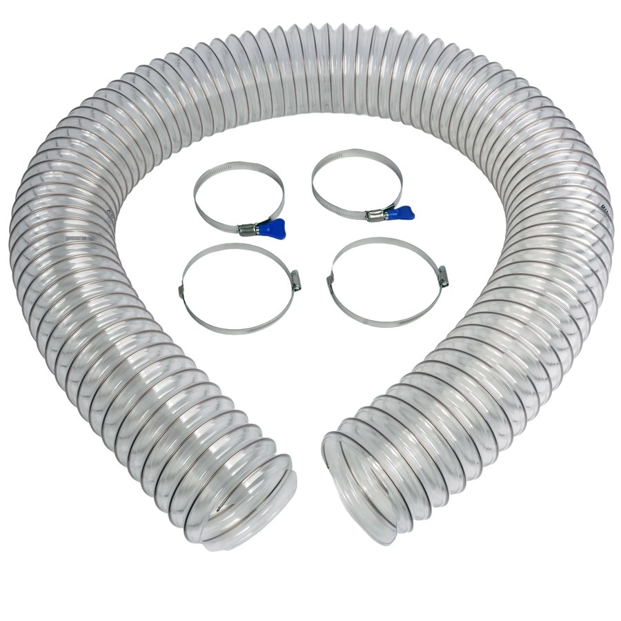
4 in. smooth-wall flex, 6 ft$35
Smooth wall flex, because ribbed hose is one of the worst offenders per foot in the whole system.
 Check price on Amazon
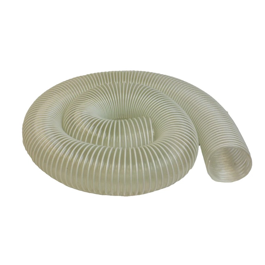
The longer smooth flex for machines further from the drop.
 Check price on Amazon
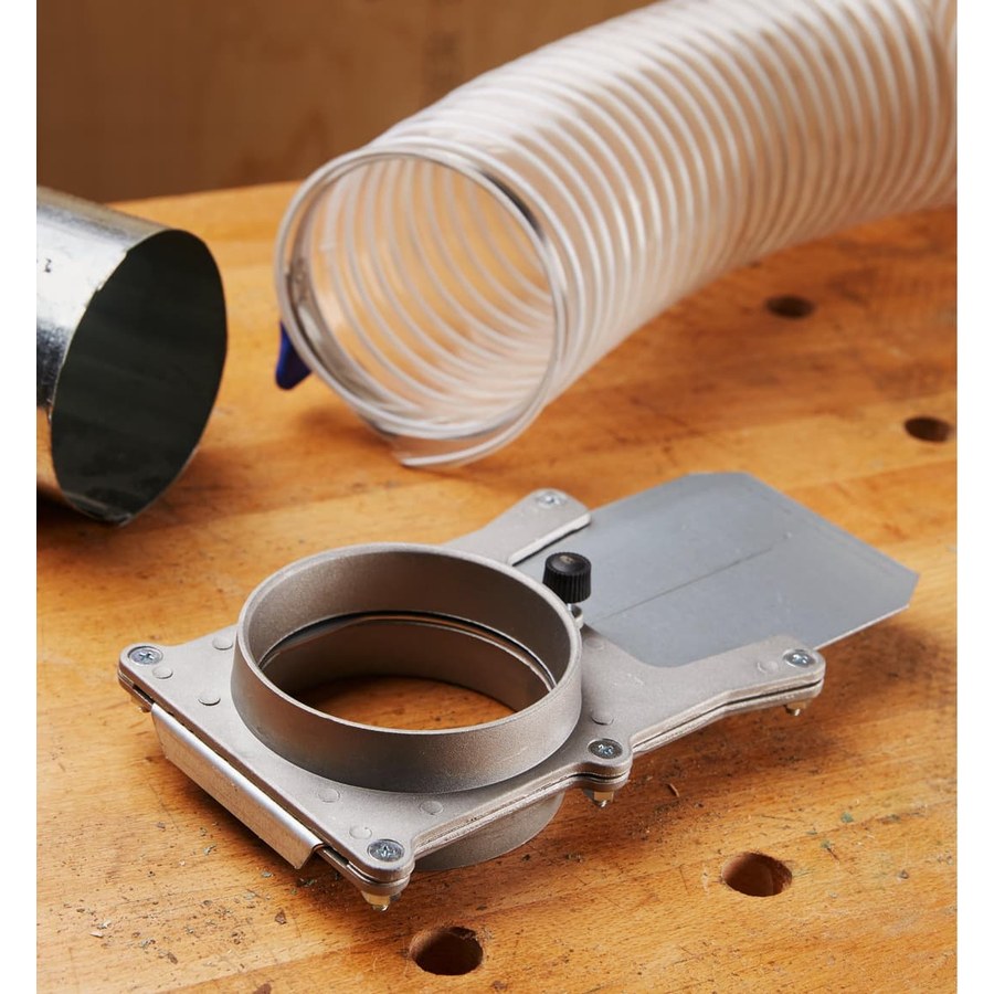
4 in. aluminum self-cleaning gate$35
Gate loss is small, but a gate that fails to seal is a leak that shows up in every calculation.
FAQ
How do you calculate static pressure in a dust collection system?
List every component on your worst branch, look up each one in a loss table like Oneida's, and add them. Rigid duct is per 5 feet, flex hose per foot, and fittings per piece. Add the filter and separator losses, apply an altitude factor if you are above sea level, and read the total against the collector's fan curve.
Do I add up the static pressure of every branch?
No. Spiral Manufacturing's method carries forward only the branch with the highest loss, plus the main, filter, and separator. That works because blast gates keep the other branches closed.
How much static pressure does a cyclone add?
Oneida suggests about 2 in. w.c. as a starting budget. The real figure depends on the cyclone model and how much air goes through it, so use the maker's number when you can get it.
What if my collector doesn't publish a fan curve?
Ask the maker for one. Without it, you can total your losses but you can't see what CFM you will get at that total. Spiral Manufacturing advises getting fan curve information before you buy a collector.